How to change the look of BricsCAD
BricsCAD allows you great flexibility in changing the way it looks and works. The first few post of this series show you how to change the look of BricsCAD; later ones concentrate on changing how it works. In short: we'll look at custom settings for BricsCAD.
This post tells you how to change the way in which BricsCAD starts up, as well as how to use the Settings dialog box to change the look of BricsCAD's user interface. For example, you can change things like the background color of the drawing area and the size of the cross hair cursor to suit you.
This post will cover:
- Starting BricsCAD
- Setting Commandline options (not available in Mac)
- Changing screen and other colors of the user interface
- Specifying support file paths
- Launching the user profile manager (not available in Linux or Mac)
Starting BricsCAD
You probably know about these ways to start BricsCAD:
- Double-click the BricsCAD icon found on your computer's desktop
- Or, on the taskbar of most releases of Windows, click the Start button, and then select Bricsys | BricsCAD V20 | BricsCAD or something similar.
- In Windows 8 and Windows 10 tablet mode, click the BricsCAD icon in the Start screen.
- In Linux, click the Main Menu button, and then select Graphics | BricsCAD
- In the MacOS dock, click the Applications folder, and then select BricsCAD
- Or, in Windows Explorer (or Linux File Browser or MacOS Finder), double-click the name of a .dwg file; this option works only when BricsCAD is the default program assigned to .dwg files.
But there are other ways to launch the program. These variations are described next.
COMMANDLINE OPTIONS
It was common knowledge in the days of the DOS and Unix operating systems that programs could use options to start up. Windows, MaOS, and Linux hide much of what goes on behind their graphical user interfaces, and so command-line options are no longer common. They are, nevertheless, still available, and here I show you how to use them with BricsCAD.
Normally, BricsCAD starts with a new, blank drawing. You can, however, have BricsCAD start with a specific file by editing a target value. BricsCAD can be made to load specific drawing files --- and other kinds of files --- as it starts; you just need to specify the file name to the OS (operating system) at the Commandline. In a moment, I'll tell you how to access that Commandline.
The following table lists the file types that can be used at the Commandline, and what they do when BricsCAD starts up:
- .CUI Loads the file that customizes the user interface
- .DLL Loads ADS/SDS or DRX/ARX programs (dynamic link libraries)
- .DSD Plots files specified earlier by the Publish command
- .DWG Opens a drawing file made by BricsCAD, AutoCAD, and other CAD programs
- .DWT Opens a template file that specifies the initial settings of new drawings
- .DXF Opens drawing interchange format files from other CAD programs
- .LSP Loads LISP and AutoLISP routines
- .MNU Loads menu files from older releases of BricsCAD and AutoCAD
- .SCR Runs a script file
- .SLD Displays a slide file
Here's how to access the Commandline in Windows and Linux. (This feature is not available on MacOS.)
On the desktop of Windows or Linux, right-click the BricsCAD icon.
Notice the shortcut menu.Select Properties.
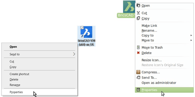
Accessing icon properties in Left: Windows 7, Right: Linux Mint
In the Properties dialog box of Windows, select the Shortcut tab.
In the Properties dialog box of Linux, select the Launcher tab.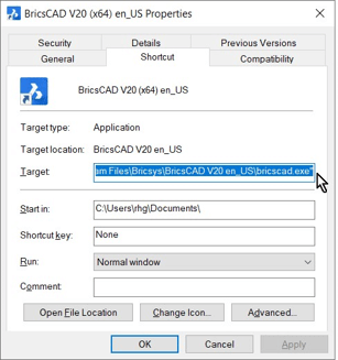
Properties dialog box in Windows.
Notice that for Windows the default command-line text is similar to the path listed below:
Target "C:\Program Files\Bricsys\BricsCAD V20 en_US\bricscad.exe"
<spanstyle="color:green">Linux is straightforward: it knows the location of programs, and so programs do not need a path.
The elements of a path, such as C:\Program Files\Bricsys\BricsCAD V20 en_US\bricscad.exe, have the following meaning:
| Path | Meaning |
|---|---|
| C: | Name of the disk drive |
| \Program Files | Name of a folder |
| bricscad .exe | Name of the BricsCAD program |
Quotation marks ( " and " ) are needed when there are spaces in the names of folders and programs
Colon ( : ) identifies the names of disk drives, such as C:
Back slashes ( \ ) separate the names of folders. The folder names may vary, depending on where BricsCAD was installed on your computer
<spanstyle="color:green">Linux has these differences from Windows:
Linux uses forward slashes ( / ) to separate folder names, rather than backs lashes
<spanstyle="color:green">The path starts from the home folder, not the root folder
Path and file names are case-sensitive in Linux, so "Documents" is a different name from "documents"
4. Here is how to start BricsCAD with a specific .dwg drawing file. The same procedure works with .dxf translation files, as well.
In the Properties dialog box in Windows, edit the text in the Target box by adding the text shown in bold:
"C:\Program Files\Bricsys\BricsCAD V20 en_US\bricscad.exe" "c:\folder\file name.dwg"
In Linux, add the path to the drawing file to the Command box:
bricscad.exe "home/<login>/Documents/My Drawings/file name.dwg"
replace "<login>"with the name by which you logged into your Linux computer. In my case, it is "ralphg," so the path looks like this:
bricscad.exe "home/<user>/Documents/My Drawings/file name.dwg"
Notice that:- The full pathname to the drawing is required
- Separate pairs of quotation marks are needed for the names of the program and the file. (Quotation marks are needed only when paths and file names contain spaces.)
5. Click OK in Windows.
In Linux, click Close.
6. Test your modification by double-clicking the BricsCAD icon. The program should start, and then open the file.
If you made an error, you will receive a complaint from a dialog box, such as this one in Linux:
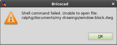
Warning message from the operating system
Reasons for errors include the following ones:
- The file name was incorrectly spelled
- The path is incorrect or incomplete
- The file is missing and does not exist
- The quotation marks are unbalanced, with the starting or ending " missing
CATALOG OF COMMAND-LINE SWITCHES
As it starts up, BricsCAD can open a number of file types, as listed by the table earlier. For instance, after starting it could run a script, or it could plot a number of drawings automatically in batch mode.
When it comes to file types other than drawings, however, you need to use a command-line switch to alert BricsCAD as to the type of file. It is called a "switch" because it switches the way BricsCAD operates; for example, the /b switch instructs BricsCAD to run a script file following start-up.
To indicate a switch, Windows uses the forward slash ( / ), borrowed from DOS. Linux uses a dash ( -- ), borrowed from Unix. (This feature is not available on Mac.)
Here is the complete list of switches that BricsCAD accepts:
| Windows | <>Linux | Meaning |
|---|---|---|
| /b filename.scr | filename.scr | >Runs an .scr script file following start up |
| /l | Suppresses the BricsCAD logo (splash screen) | |
| /ld app .arx | -ld app .arx | Loads an ARx, BRx, or DRx application |
| /p profile.arg | -p profile.arg | Loads an alternate user profile |
| /pl plotlist .dsd | -pl plotlist .dsd | Plots silently in the background |
| /s path | -s path | Specifies alternative search paths for support files |
| /t path | -t path | Specifies the path and name of a .dwt template file |
The following switches apply to Windows only; Linux does not support COM:
| regserver | Registers BricsCAD’s COM (common object model) |
|---|---|
| unregserver | Unregisters COM |
You can use any number of switches in a row to make multiple things happen as BricsCAD starts up. For example, it could plot a number of drawings and then open a specific template file.
Let's now go through a detailed description of each switch.
No Switch -- Load Drawings
BricsCAD uses no switch to load one or more .dwg and/or .dxf files specified at the OS Commandline:
"c:\program files\bricsys\bricscad\bricscad.exe" "c:\my documents\filename.dwg" c:\dwg\filename.dxf
B Switch -- Script Files
The b switch specifies the name of a .scr script file to run immediately after BricsCAD starts. The "b" is short for batch. The switch is followed by the path and name of the script file. Here is an example of the usage in Windows:
"c:\program files\bricsys\bricscad\bricscad.exe" /b "c:\BricsCAD\script file.scr"
(See the later post on scripts to learn how to write your own script files.)
L Switch -- No Logo
The l switch suppresses the logo at startup. The "l" is short for logo. This means that the splash screen bearing the BricsCAD name and version number does not appear. Notice that this switch appears by itself; no path or file name is associated with it.
In Windows, it looks like this:
"c:\program files\bricsys\bricscad\bricscad.exe" /l
In Linux, it looks like this:
bricscad.exe -1
LD Switch -- Application Load
The ld switch specifies the names of applications to load, specifically those written with Bricsys's
BRx, the ODA's DRx and Tx, or Autodesk's ARx application programming interfaces --- APIs. The "ld" is short for load. This switch is useful when you want to load add-on programs right away as BricsCAD starts.
"c:\program files\bricsys\bricscad\bricscad.exe" /ld "appname.brx"
S Switch -- Search Support Paths
The s switch specifies alternative search paths for support files. The "s" is short for search. This switch is useful when you want to load linetypes, patterns, and menu files provided by clients; you don't want to mess up your own setup, and so you place these files in their own folder, and then point to the folder with this switch.
Notice that this switch specifies only paths, not any file names:
"c:\program files\bricsys\bricscad\bricscad.exe" /s "c:\client\support"
You can specify multiple paths by separating them with semicolons ( ; ), like this:
"c:\program files\bricsys\bricscad\bricscad.exe" /s "c:\client1\support;c:\client2\support"
P Switch -- User Profiles
The p switch loads an .arg user profile file. The "p" is short for profile. This file changes the way that BricsCAD looks, as described more fully later in this post.
Here is an example of its use:
"c:\program files\bricsys\bricscad\bricscad.exe" /p "c:\bricscad\myui.arg"
TIP BricsCAD includes a separate utility command for creating and editing user profiles, ProfileManager, described at the end of this post.
PL Switch -- Batch Plotting
The pl switch plots drawings in the background without showing the BricsCAD program window. The "pl" is short for plot. It reads the files to be plotted from .dsd files, which are created earlier by the Publish command in BricsCAD.
Here is an example of its use:
"c:\program files\bricsys\bricscad\bricscad.exe" /pl "c:\bricscad\plotlist.dsd"
BricsCAD reads the .dsd file and then plots the drawing according to the instructions contained therein. The .dsd file saved by the Publish command specifies the file name, layouts, page setups, plotter and printer names, orientation, plot scale, number of copies, optional plot stamp, and the order in which to plot the files.
The .dsd extension is optional. When the file name is missing, however, BricsCAD simply exits.
TIP When BricsCAD starts with the /pl switch, it ignores the setting of SingletonMode, and so multiple instances of the program can be launched irregardless.
T Switch -- Template Files
The t switch opens BricsCAD with a new drawing based on the .dwt template file specified by this switch. The "t" is short for template. This file changes the way that the drawing initially looks.
Here is an example of its use:
"c:\program files\bricsys\bricscad\bricscad.exe" /t "c:\drawings\officetemplate.dwt"
Regserver and Unregserver Switches
The regserver and unregserver switches register and unregister BricsCAD's COM common object model. They operate only with Windows, because Microsoft does not provide COM for Linux or MacOS systems.
OTHER STARTUP CONTROLS
(new in V20) BricsCAD offers variables that control which elements are displayed during startup. These elements include the Launcher dialog box and the Start screen. Note that the splash screen is controlled by the /l switch described above. (Functions new in V20 are shown in red.)
GetStarted variable toggles the display of the Launcher dialog box:
TABLES NO BORDER:
| GetStarted | Meaning | |
|---|---|---|
| 0 | Do not display | |
| 1 | default | Display the Launcher dialog box |

The Launcher dialog box
Startup variable displays one of several startup dialogs:
| Startup | Meaning |
|---|---|
| 0 | Start new drawing with template file specified by BaseFile |
| 1 | Display Startup dialog box |
| 2 | Display the Start window without the ribbon (see figure below) |
| 3 | (default) Display the Start window with the ribbon |

The Launcher dialog box
Changing the Colors of the User Interface
BricsCAD allows you to change some aspects of its user interface directly, while other aspects are controlled by Windows. With BricsCAD, the changes are made through the Settings dialog box.
THEME COLOR
(new in v20) You can change the colorization of the entire interface of BricsCAD between light and dark. This is called the "theme color." Prior to V20, the theme color was light; as of V20, the default is dark. The change is made with the ColorTheme setting:
In BricsCAD, you the change a settings like this:
Enter the Settings command. Notice the Settings dialog box.
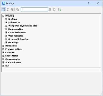
Settings dialog box
In the dialog box, enter "theme" in the search field. If the field turns orange, it's because you have misspelled the word(s). Notice that dialog box jumps to the UI Color Theme settings.

Searching for "theme" variable
Click the droplist adjacent to UI Color Theme, and then choose a theme, either light or dark:

Choosing a different color for the paper space background
The changes you make in the Settings dialog box have an immediate effect in BricsCAD, and so the theme color changes as soon as you select the other one.
There is no "OK" or "Apply" button to click, because changes take effect immediately. Instead, click the dialog box's Close button:

Closing a dialog box
Background Color
The first change I always make to a new CAD installation is to the background color of the drawing area. Usually, it are colored black by default.
(History note: Black was the traditional color in the days when CAD ran on the DOS operating systems. Some users prefer the dark color, because entity colors look more vibrant against it. Others prefer a white background, because that most closely resembles the paper upon which the drawing will be printed. I prefer the white background color.)
In BricsCAD, you the change background color like this:
1. In the Settings dialog box, enter "background color" in the search field. Notice that the dialog box jumps to the Background Color variable.

Searching for "background color" variableClick the droplist adjacent to Background Color, and then choose a color, such as "White."

Choosing a different color for the paper space background.
TIP If the color you are looking for is not on the droplist, then click Select Color to access the Color dialog box. Choose a color from the dialog box, and then click OK.
In a similar manner, you can make changes to the background color of paper space (layouts) --- and many other areas of BricsCAD. For layouts, this is done with the Paper Space Background Color option. (It affects the color of the "paper" in layouts, not the color of the background.)
If, after exiting the Settings dialog box, you want to revert the value, just enter the U (undo) command.
TIP The changes you make to the color of the cursor's axes have no effect on the colors of the UCS icon's axes, which cannot be customized.
Changing Cursor Color and Size
In the drawing area, BricsCAD displays a "tri-color" crosshair cursor that has a different color for each of the axes. The UCS icon follows the same color scheme.

SETTINGS AT THE COMMANDLINE
Many times, using the BricsCAD Commandline is faster than the dialog box. You can avoid opening the Settings dialog box (and then searching for variable names) by changing values directly at the command prompt: just type the name of a variable.
For example, I find it faster to change the size of the crosshair cursor by entering the following variable name at the command prompt, and then changing its value:
: cursorsizeNew current value for CURSORSIZE (1 to 100): <3>: 100
By default, the colors are assigned as follows:
| Axis | Default Color | Color Number |
|---|---|---|
| x | Red | 11 |
| y | Green | 112 |
| z | Blue | 150 |
You change its color and size of the crosshair cursor like this:
n the Setting dialog box's Program Options section, enter "x axis color" in the Search field.
Choose X axis Color, and then change its color.
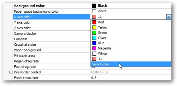
Changing the color of the cursor axes.
Repeat for Y axis Color and Z axis Color.
If you wish, you can also change the size of the cursor with the Crosshairs Size setting. The default is 3, which means 3% of the screen size. A value of 100 (percent) makes the cursor full-size.

Changing the size of the crosshair cursor
Normally, the crosshair cursor appears only when you use a drawing or editing command. If you want the crosshair cursor to always be on, then turn on the "Pointer defaults to crosshairs" option of the Always Use Crosshairs option.
DISPLAY SETTINGS
Here are settings that affect the BricsCAD display:
| Display Setting | Variable Name | Meaning |
|---|---|---|
| Background Color | BkColor | Sets the background color of the model space drawing area |
| Paper Space Background Color | BkColorPs | Sets layout mode’s paper color |
| X Axis Color | ColorX | Specifies the color of the crosshair cursor’s x axis |
| Y Axis Color | ColorY | Specifies color of crosshair cursor’s y axis |
| Z Axis Color | ColorZ | Specifies the color of the crosshair cursor’s z axis |
| Always Use Crosshairs | AlwaysUseCrosshair | Displays the crosshair cursor in place of the pointer cursor |
| Crosshairs Size | CursorSize | Sizes the cursor cross hairs, as a percentage of the drawing area |
Interface Parameters Controlled By the OS
Operating systems control some of aspects of the BricsCAD's user interface, such as fonts and colors used by menus. This level of personalization is not available in Windows 8 or 10. In Windows 7, follow these steps:
Right-click the desktop, and then select Personalize.
Click Windows Color and then choose Advanced Appearance Properties.
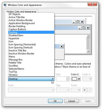
Customizing the appearance of Windows
In the Window Color and Appearance dialog box, change the fonts and color user interface elements.
In Linux, follow these steps:
Right-click the desktop, and then select Change Desktop Background.
Click Fonts to change the default fonts used for the interface.
Choose Theme to set the overall look and color of dialog boxes and other UI elements.
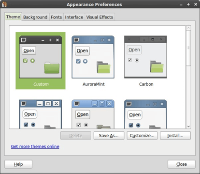
Customizing the appearance of Linux
In MacOS, follow these steps:
From the dock, choose Settings.
In the System Preferences folder, choose General.
Make changes as desired.
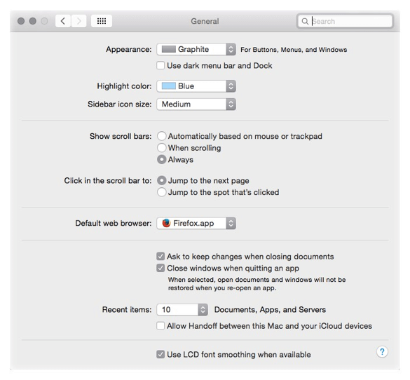
General settings for MacOS
SNAP MARKER OPTIONS
Snap markers display information at the cursor about the current object (or entity) snap modes. BricsCAD allows you to choose the color, and other options, for snap markers and snap cursors.
Some of the settings are illustrated below:

Parts of snap markers that can be customized.
Most of these options are found near the end of the Display section of the Settings dialog box --- and not the Snap/Grid section!

Settings for snap markers
Other snap-related options are found at the start of the Snap Tracking section:

Additional settings for snap markers
Finally, there are aperture options in the Entity Snaps section:

Settings for the aperture
HYPERLINK CURSOR OPTIONS
Entities can contain hyperlinks, which are links to Web sites and other documents. When the cursor passes over them, a tooltip reports the name of the link. A shortcut menu that displays options useful for working with hyperlinks, which are added with the Hyperlinks command.) The hyperlink menu and the tooltip are illustrated below:

Left: Hyperlinks options added to the right-click menu. Right: Tooltip reporting hyperlink attached to a circle.
The Settings dialog box has the options for hyperlinks near the end of the Display section.

Settings for hyperlinks
DYNAMIC DIMENSION OPTIONS
Dynamic dimensioning shows the lengths and angles of entities as they are being drawn. You turn on this function by clicking DYN on the status bar.

Elements of dynamic dimensions.
Through the Settings dialog box, you can adjust the look of dynamic dimensions. The quick way to access these is by right-clicking DYN on the status bar and then choose Settings.

Settings for dynamic dimensions
Support File Paths
BricsCAD uses a number of folders in which to store support files, such as those needed for fonts, on-line help, and hatch patterns. BricsCAD locates the support files by consulting "paths" to the folders. A path specifies the name of the drive and the folder, such as c:\BricsCAD. There are several reasons why you may want to change the file paths that BricsCAD uses:
- Your firm has clients with different standards for fonts, layers, and so on
- You are a third-party developer, and need to have paths pointing to sets of different files
- You import drawings from other CAD packages, and need to map different sets of fonts via .fmp files
You are not limited to specifying one single path; you can have BricsCAD search along multiple paths, including those on networks. Multiple paths are separated by semicolons (;).
Here is how to change paths and file locations:
Enter the Settings command.
In the Search field, enter "support file." Notice the Files section.
To change a path, select a path adjacent to a heading. For example, click the field next to Support File Search Path.
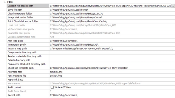
All of the paths to files.
Notice the Browse button, click it.
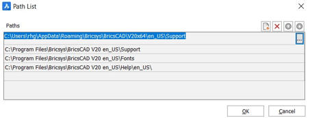
Adding and removing paths.
Notice that BricsCAD displays the Folder List dialog box, which lets you add, remove, and reorder multiple paths. Choose a path, and then close the file dialog box.
The Path List dialog box has buttons for controlling the list of folder names:
| Button | Name | Meaning |
|---|---|---|
< |
Add Folder | Adds a black entry to the list. |
 |
Remove Folder | Removes the selected folder from the list. Caution! BricsCAD does not ask for deletion confirmation. If you erase a folder by accident, click the Cancel button to exit the dialog box with no changes preserved. |
 |
Move Up/Down | Moves the selected folder up or down the list. |
TIP BricsCAD searches paths by the order in which they are listed this order, BricsCAD will find files in folders listed higher up sooner. For example, search folders on your computer before searching the network or the other way around.
To add a folder, follow these steps:
Click the Add Folder button. Notice that a black entry is added to the dialog.
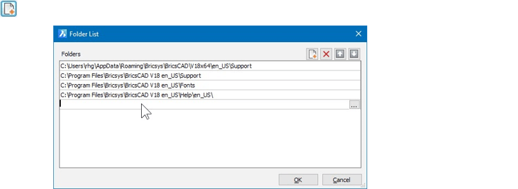
Blank line added to folders list.
Click the Browse button. In Windows, notice the Browse for Folder dialog box. (In Linux, the Choose a Folder dialog box appears.)
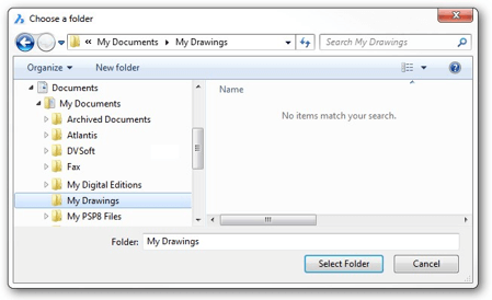
Choose a Folder dialog box in Windows
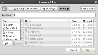
Choose a Folder in Linux
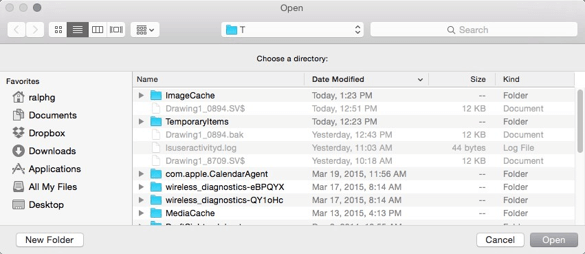
Open a folder in MacOS
You can choose a folder on your computer, or from a computer connected over the network. Internet locations cannot, however, be chosen.
__TIP__ To create a new folder while in the files dialog box, just click the __New Folder__ (or Create Folder) button, and then give it a name.
- Click OK sufficient times to exit dialog boxes. Notice that the selected path is added to the list.
SUMMARY OF FILES SETTINGS
Here are some details on the paths and support files specified through the Setting dialog box's Files section. You can modify all paths, except for ones that are read-only, such as "Local Root Prefix" and "Menu Name."
System variable names are shown in small caps; those in red are specific to BricsCAD; those in black are found in both BricsCAD and AutoCAD.
Files (and Paths)
Support File Search Path (srchpath) --- folders that store fonts, customization, plug-ins, blocks, linetypes, and hatch patterns. You can specify multiple paths, each separated by a semi-colon.
Save File Path (savefilepath) --- path for storing temporary and automatically saved files.
Cloud Temporary Folder (cloudtempfolder) --- folder in which BricsCAD stores temporary download files from its online 24/7 service (formerly called "chapootempfolder").
Image Disk Cache Folder (imagecachefolder) --- folder which temporarily stores cached raster files placed as images in drawings.
Point Cloud Disk Cache Folder (pointcloudcachefolder) --- folder which temporarily stores point cloud files placed in drawings.
Local Root Prefix (localrootprefix; read-only, set by Windows) --- folder in which BricsCAD stores support files for the program specific to the local computer.
My Documents Root Prefix (mydocumentsprefix; read-only, set by Windows) --- folder in which BricsCAD accesses the logged-in user's specific documents and other files.
Roamable Root Prefix (roamablerootprefix; read-only, set by Windows) --- folder which stores support files for the program when the user signs onto other (roamed) computers.
Version Customizable File (versioncustomizablefiles; ready-only, set by Bricsys) --- current version number of CUI and PGP files.
Xref Load Path (xloadpath) --- path to temporary copies of demand-loaded xrefs.
Temporary Prefix (tempprefix) --- path to the folders in which BricsCAD stores temporary files, such as automatic backup files (filename.sv$).
Texture Map Path (texturemappath) --- path to the folder holding texture map files.
Components Directory Path (componentspath) --- path to component files used for mechanical parts.
Render Material Directory Path (rendermaterialpath) --- path to material files used for rendering.

Additional specifications for paths
Render Material Directory Path (rendermaterialspath) --- path to material files used for previews.
Details Directory Path (detialspath) --- path to details files used for generated drawings.
Parametric Blocks 2D Directory Path (parametricblocks2dpath) --- path to where BricsCAD stores 2D parametric blocks.
Sheet Set Template Path (sheetsettemplatepath) --- path to the folder holding sheetset template files.
Alternate Font (fontalt) --- font to use when a font cannot be found. Default is the simplex.shx font file.
Font Mapping File (fontmap) --- file that maps fonts. When a font cannot be found, BricsCAD consults this .fmp file for the name of a matched font; if the matched font cannot be found, it uses the alternative font specified above.
TIP If unexpected fonts appear for text in a drawing, this means that BricsCAD was unable to find the correct fonts. Either use the default.fmp file to match equivalent fonts, or add the appropriate path to the Fonts path.
Hyperlink Base (hyperlinkbase) --- default path for relative hyperlinks in drawings.
Menu Name (menuname; read-only, specified by BricsCAD) --- path and name to the menu file.
Audit Control (auditctl) --- toggles whether the Audit command creates reports in .adt files.
Audit Edit Count (auditerrorcount; read-only, set by BricsCAD) --- reports the number of errors found in the last audit of a drawing file.
Recent Path (recentpath) --- most-recent path used to access a file.
Project Paths
Project Search Path (projectname) --- paths to the folders in which BricsCAD searches for raster image files and externally-referenced drawing files.
Project Search Paths (projectsearchpaths) --- names of projects and related paths. Click button to create new project settings.
TIP Projects allow you to assign one or more paths to a drawing project.
Printer Support Paths and Files
Plot Styles Path (plotstylepath) --- path to the folders in which BricsCAD accesses .ctb and .stb plot style files.
Plotter Configuration Path (plotcfgpath) --- path to the folders in which BricsCAD stores .pc3 plot configuration files.
Plot Output Path (plotoutputpath) --- path to the folders in which BricsCAD stores plot files.
Print File (printfile) --- default name to use plot files; "." means to use the drawing's file name.
Templates Paths and Files
Template (basefile) --- name of the .dwt or .dwg drawing file used to start new drawings upon starting BricsCAD or when using the New command.
Template Path (templatepath) --- path to .dwt template files.
Sheet Set Template Path (sheetsettemplatepath) --- path to the folder holding sheetset template files.
Default New Sheet Template (defaultnewsheettemplate) --- name of the .dwg or .dwt file from which to create new sheets.
BM Form Template Path (bmformtemplatepath) --- path the folder holding template drawings for BricsCAD Mechanical forms.
Tool Palettes Path
Tool Palettes Bar State (tpstate; read-only, set by BricsCAD) --- reports whether the Tools Palette is open or closed.
Tool Palettes Path (projectname) --- path to the folder holding XTP tool palette definition files.
Dictionaries Section
Custom Spelling Dictionary (dictcust) --- path and name of the .cus file used to store words added by the user during the Spell command. No, it has nothing to do with cussing.
Main Spelling Dictionary (dctmain) --- path and name of the .dic file used for checking the spelling of text in drawings.
Log Files Paths and Files
Log File Mode (logfilemode) --- toggles the creation of .log files, which record all keystrokes entered at the command prompt.
Log File Name (logilename;read-only, set by BricsCAD --- name of the file with which to record the command-line text, after the LogFileOn command turns on logging. When this entry is blank, log files are named after the drawing.
Log File Path (logfilepath) --- path to the folder that stores log files.
Cloud Log (cloudlog) --- determines whether 24/7 log files are stored (formerly called "chapoolog").
File Dialogs
Remember Folders (rememberfolders) --- default path for file-oriented dialog boxes, such as Open and Save As. Options are:
- 0 --- Use Start In Path uses the Start In path specified in the Windows Properties dialog box
- 1 --- Use Last Path Used uses the path stored in the Recent Path option
Use Standard Open File Dialog (usestandardopenfiledialog) --- toggles the display of path icons in file-related dialog boxes.
Drawings Path (drawingpath) --- path to the folders in which to search for .dwg drawing files.
Blocks Path (blockspath) --- path to the folders in which search for .dwg block files.
Thumbnail Preview Image Size (thumbsize) --- ranges from 64×64 pixels to 2560×2560.
Preview Window in Open Dialog (previewwndinopendlg) --- toggles the display of the preview image of .dwg files in dialog boxes.
Preview Type (projectname) --- view to show in thumbnails:
- Last Saved View of the drawing last time it was saved
- __Home View __of the drawing in its default state
Places Bar (Windows only)
First thru Fourth Folder (placebarfolder1 thru placebarfolder4) --- specifies the order which places appear in file-related dialog boxes. Choose from the following places:
| PlaceBarFolder | Meaning |
|---|---|
| 1 | Desktop |
| 2 | My Computer |
| 3 | My Documents |
| 4 | Favorites |
| 5 | Network |
| 6 | My Recent Documents |
Drawings Path (drawingpath) --- lists additional folders for Open and SaveAs commands.
Reusing User Preferences
After you customize BricsCAD through the instructions given by this book, you can save the changes to .arg files. You can makes changes to how BricsCAD looks and works, and save them, and then reuse them later.
For example, here are some reasons why you might want to create .arg files:
Projects. It may be necessary to customize BricsCAD for specific projects. Through .arg files, you can BricsCAD to look in project-specific folders, use specified plot settings, and so on.
Portability. Through .arg files, you can make any copy of BricsCAD your own. Import the .arg file into the CAD program running on another computer, activate it, and when BricsCAD restarts, it will look just like your own. In this case, you might be setting the size of the cursor and colors of user interface elements, such as the background color of the screen.
The .arg file stores settings in the following areas of BricsCAD:
- All settings that are reported by the Settings dialog
- All settings that are stored in the Windows registry
- Plotter settings used for model space
- Settings made in dialog boxes
- Project settings
- Recent paths
- Status bar settings
- Tip of the Day setting
- Toolbar settings
To make it easier to work with .arg files, BricsCAD includes the User Profile Manager utility program. It displays a dialog box that lets you save and recall settings. More importantly, the dialog box's Start button launches BricsCAD with the selected user profile. (This is like using the /p switch discussed earlier.)
TIP The .arg file format used by BricsCAD is compatible with AutoCAD. This means you can swap user profiles between AutoCAD and BricsCAD.
LAUNCHING THE USER PROFILE MANAGER
You launch the manager from inside or outside BricsCAD:
- Inside of BricsCAD through Tools | User Profile Manager, or enter the ProfileManager command.
- Outside of BricsCAD through the Windows Start button: All Programs | Bricsys | User Profile Manager. (This option is not available on Linux or Mac.)
Notice the dialog box that appears. On the right is a column of buttons for creating and editing user profile names. The buttons have the following meaning:
- Create... creates new profiles, prompting you for a name. It uses the current settings found in BricsCAD.
- Set Current sets the selected profile as the current one. The next time BricsCAD starts, it will use this profile.
- Copy... makes a copy of a selected profile.
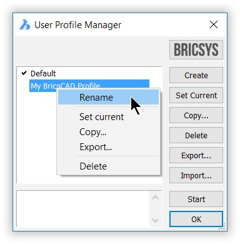
- Delete removes the profile. (In-use profiles cannot be erased.) Export... exports the selected profile as an .arg file.
- Import... imports .arg files in to this copy of BricsCAD.
- Start launches BricsCAD with the selected user profile.
- OK closes the dialog box.
To rename a profile, right-click its name, and then choose Rename from the shortcut menu.

