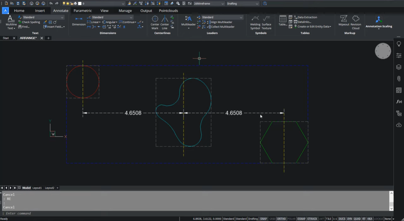
The ARRANGE command is an all-new feature in BricsCAD® V22. You can use it to spatially organize sets of 2D or 3D entities by aligning or distributing them along the axis of your current UCS.
Previously you had to arrange objects using eight different options in X, Y, and Z axis directions using several MOVE commands. The new ARRANGE command boosts productivity, saving you time by enabling you to organize entities in a faster and more flexible way!
Read on to discover Explore this video to learn more and get a full understanding of this new time saving command.
The Arrange command in BricsCAD spatially organizes sets of 2D or 3D entities by aligning or distributing them along the axis of the current UCS.
This new arrangement of entities is defined based on the bounding boxes of the selected entities.
The bounding box of an entity is the smallest box which contains an entity. The gray rectangles in dashed lines indicate the bounding box.
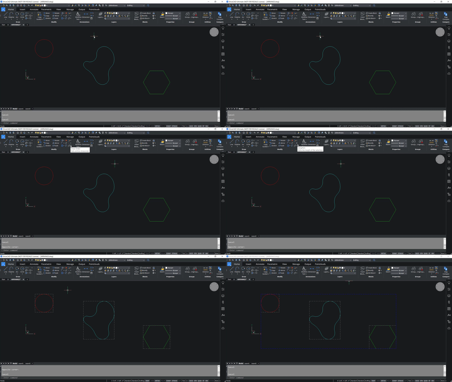
Similarly, the bounding box of a selection is the smallest box which contains all the selected entities. If I select all these entities, the bounding box of the selection is indicated with a blue dashed rectangle.
First there are the main bounds that are attached to the selection bounding box. Next, we have secondary bounds that are attached to the bounding boxes of each entities in the selection.
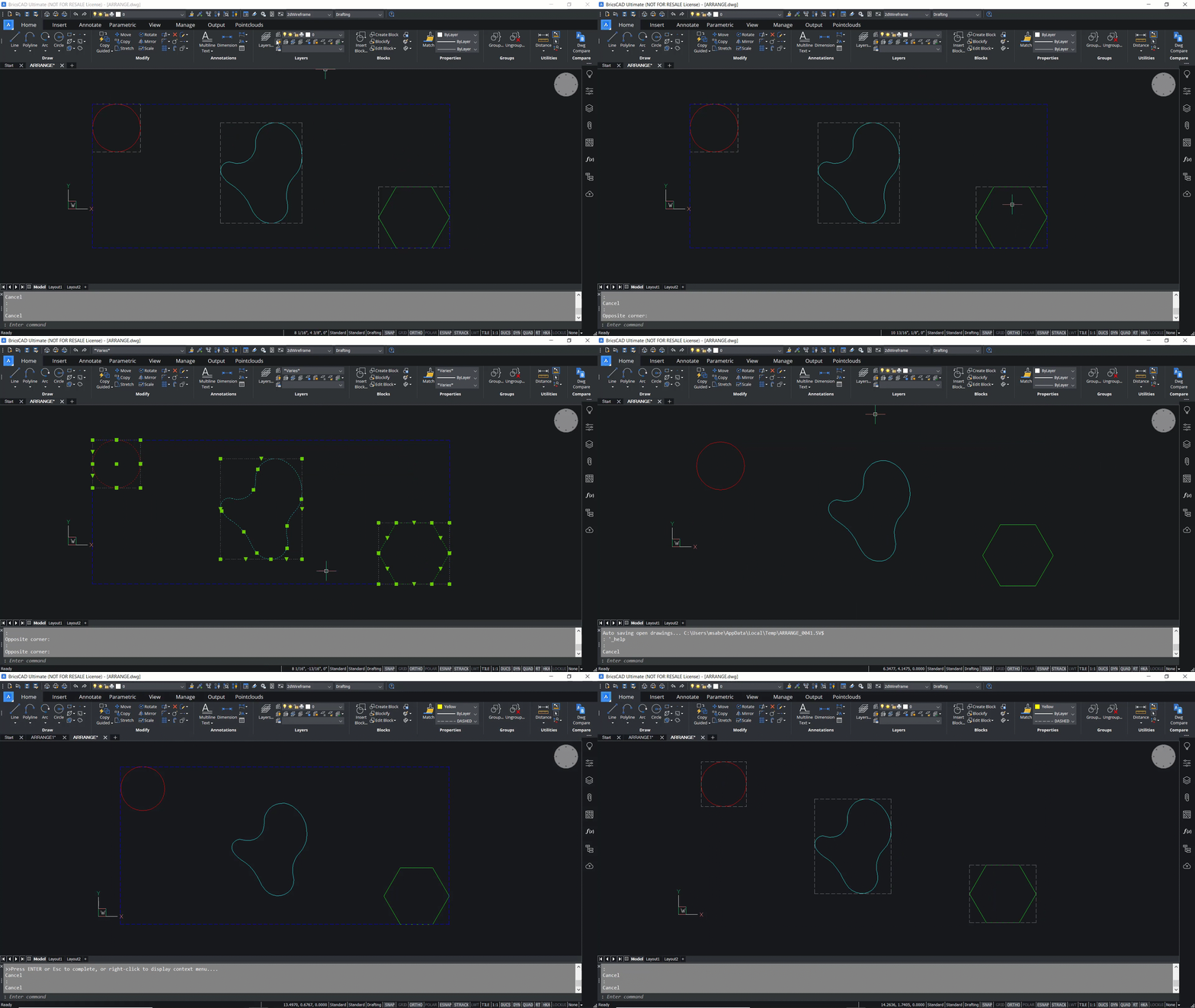
Let’s launch the Arrange command and explore this further.
You’ll be asked to select the entities to arrange. Choose these entities using a window, and click Enter. Next, you have to choose a direction which is specified using the X, Y, and Z axis of the UCS.
When you choose an axis, the entities will only be moved along this axis.
In this example, we’ve selected the X axis. We can now choose from one of the eight arrangement options. For example, the lower line aligns the lower bounds of the entities with the lower bound of the selection box. The lower bound is defined by the smallest coordinates along the specified axis.
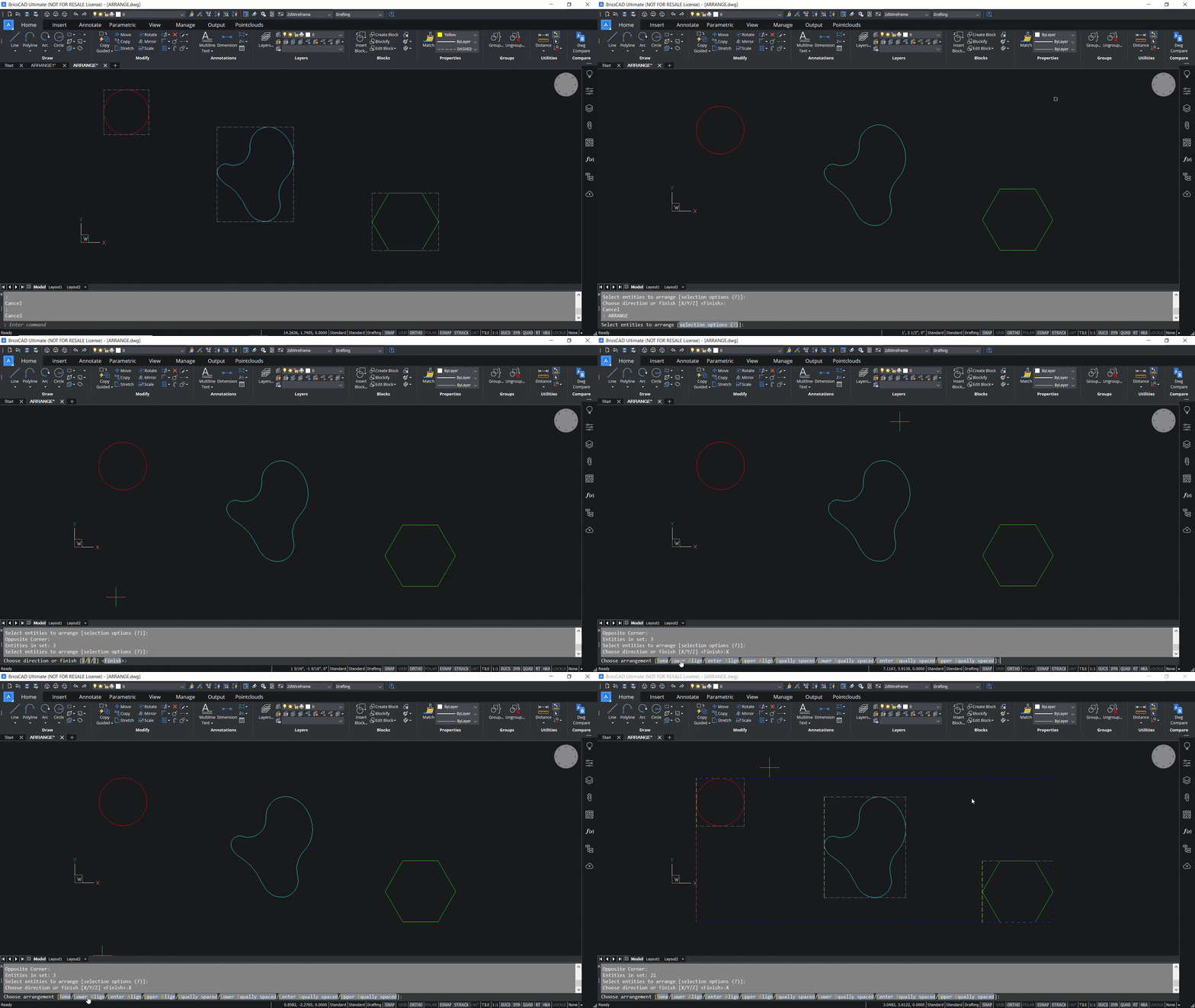
Let's try to understand this concept by using bounding boxes as references.
Lower bounds of entities are indicated with yellow dashed edges and the lower bound of the selection set is indicated with a dashed edge. When you execute lower align the lower bounds of the entities will get aligned with the lower bound of the selection set, because the lower bound is defined by the smallest coordinate in the X direction. Click on lower align and you can see that the lower bounds of the entities and the selection set is perfectly aligned.
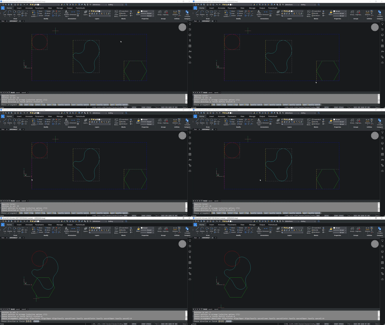
The next step is to click on X again, then click on upper align. In upper align the upper bounds of the entities and the selection set will get aligned. The upper bound is defined by the highest coordinate along the specified axis. We click on upper align and you can see that the upper bounds are perfectly aligned. Now we click on X, and none. In the none option, the entity will not get arranged.
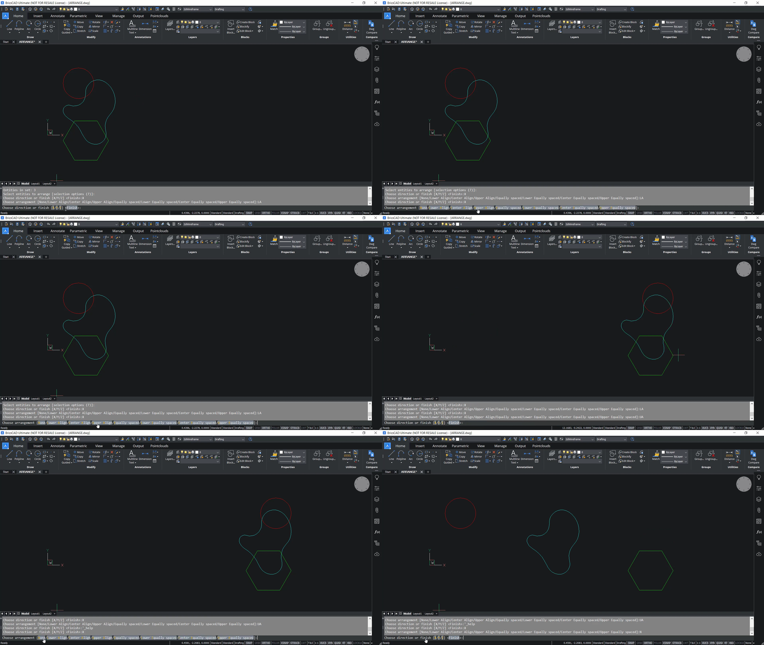
If the arrangement is already done, the entities will be moved to the original position. We click on X again, then click on center align. In center align the center bounds of entities and the selection set will get aligned in the X direction.
The center bound is located between the lower and upper bounds at the same distance from each of them. In the example below, the yellow dashed lines indicate the center bounds of individual entities and the magenta dashed line indicates the center bound of the selection set. We click on center align and you can see that the center bounds are aligned. Next, we click on X, then equally spaced.
In this arrangement, the entities will get arranged in such a way that the gap between the entities will be of the same size along the X axis, and that is clear from this illustration.
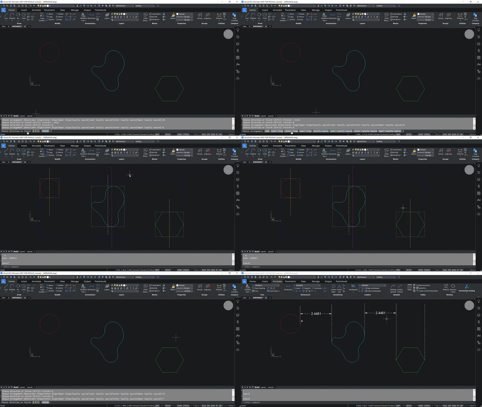
Now we click on X and lower equally spaced.
In this option the distance between the lower bounds of the consecutive entities will be the same along the X axis, as you can see below. The distances between the lower bounds of these entities are the same in the X direction. We click on X, and center equally spaced. In this case the distance between the center bounds of the consecutive entities will be the same along the X direction. You can see that the distance between the center bounds of the consecutive entities are the same in the X direction.
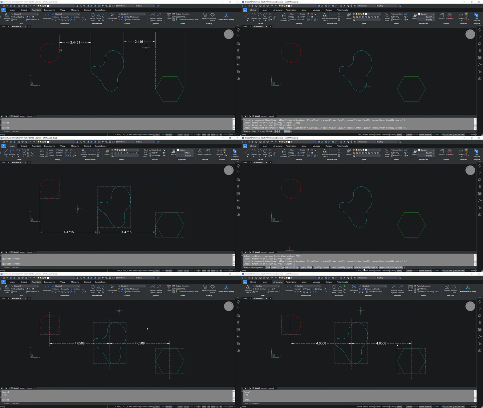
We click on X again, then on upper equally spaced. In this case the distance between the upper bounds of the consecutive entities will be the same along the X direction, as you can see in the video below.
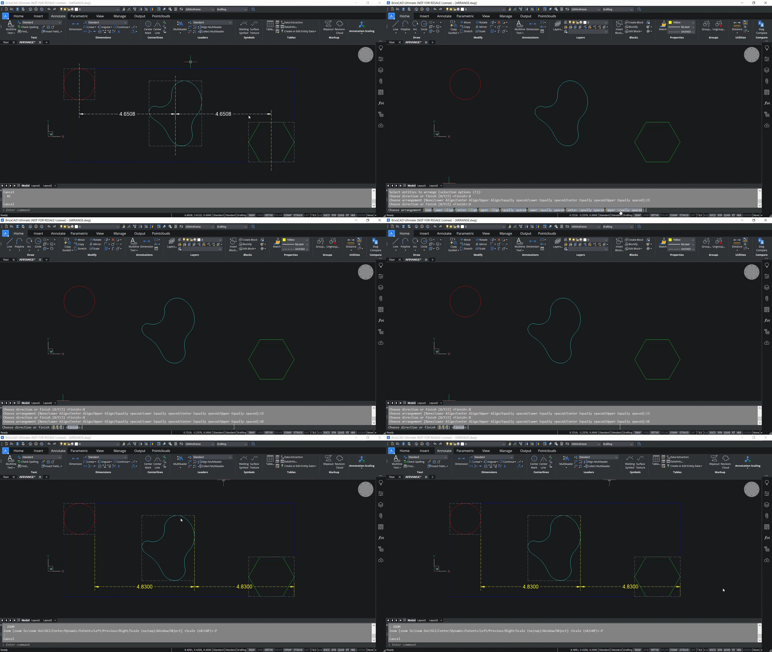
You will have access to eight arrangement options in the X direction, and you’ll get the same options in Y and Z axis directions. You can click on Y to arrange along the Y axis. In the example below, we click on lower align. When lower align is selected, the lower bounds of the entities gets aligned with the lower bound of the selection set. The lower bound is determined by the smallest coordinate in the Y axis direction.
In this illustration the yellow dashed lines indicate the lower bound of the entities and the magenta dashed line indicates the lower bound of the selection set in the Y direction. In lower align these two bounds will get aligned. We click on lower align and you can see the result below.
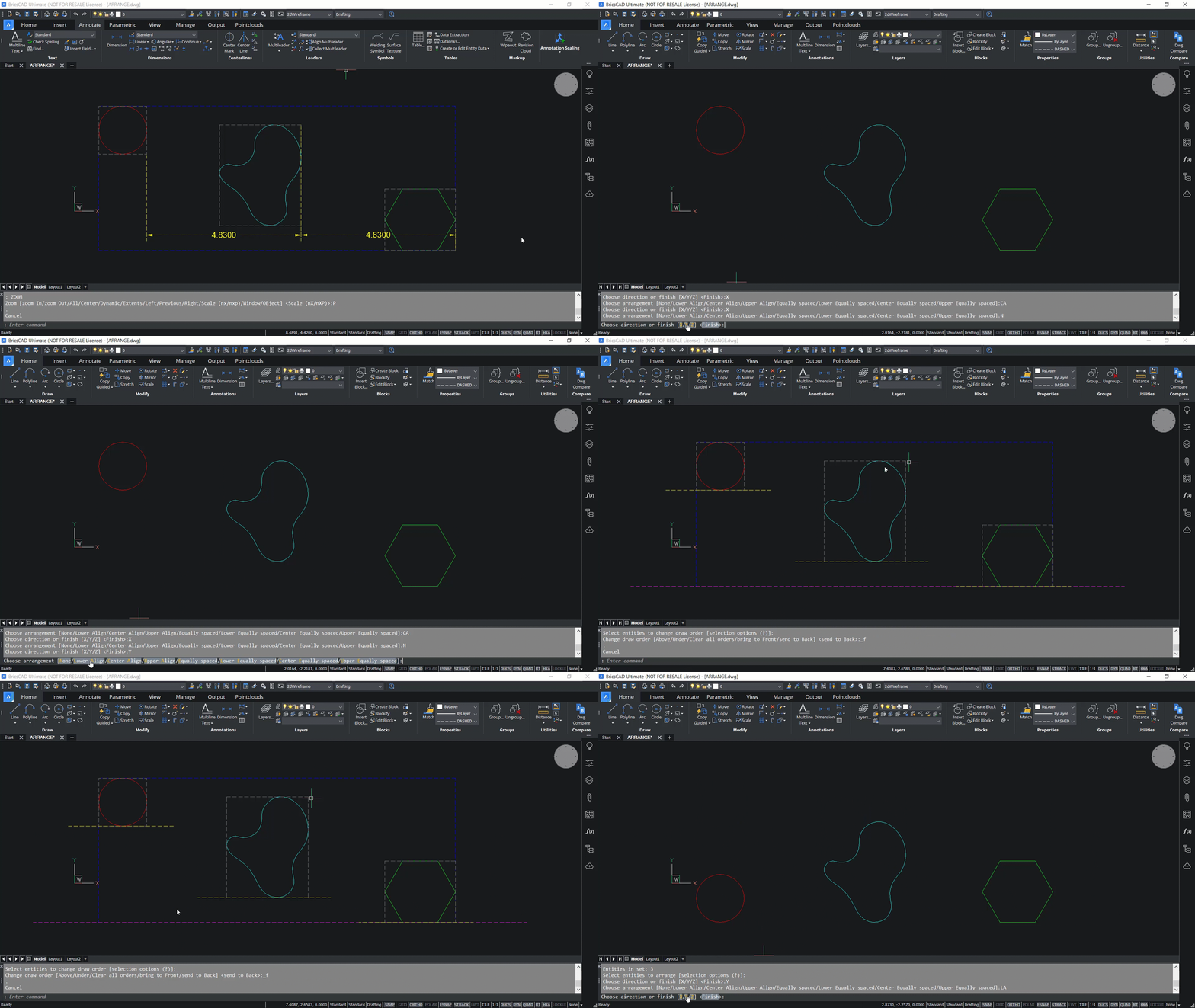
Now we’ll click on Y again and the upper align aligns the upper bounds of the entities with the upper bound of the selection set. Upper bound is determined by the maximum Y coordinate in the Y direction. When we select a parallel line, you can see the result in the video below. The upper bounds of the entities and the selection set are aligned in the Y direction.
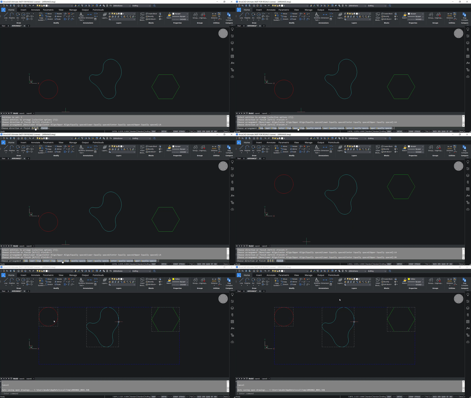
If we click on Y and center align you can see that the center bounds of the entities will get aligned with the center bound of the selection set in the Y direction. To move these entities in the Y direction you can select the Move command, then click Arrange command, select your entities, click on Y, then click on equally spaced, and finally click Enter.
Now you can see that the distance between these entities is the same in the Y direction.
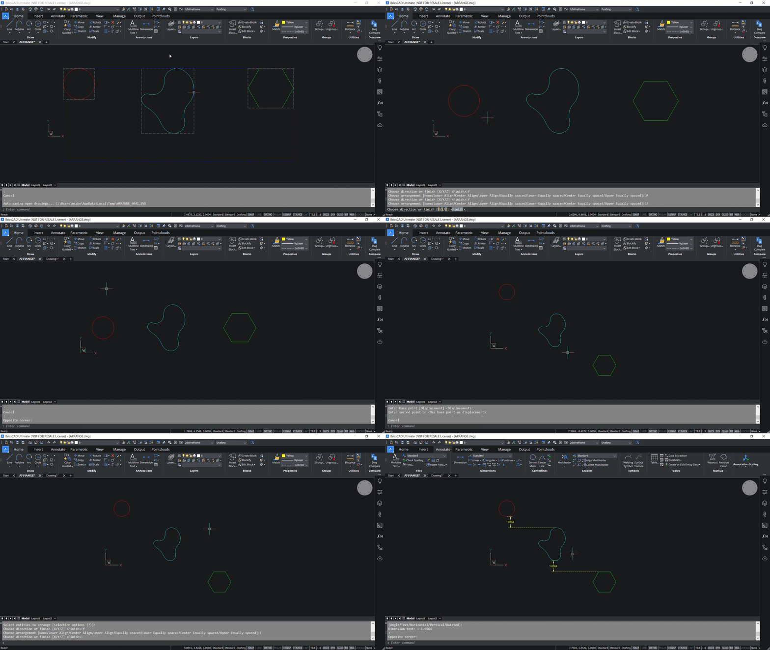
Further options you have include lower equally spaced, center equally spaced, and upper equally spaced. Each of these options are similar to what we have already seen in the case of X axis. The only difference is that the arrangement is done along the Y axis. You can also arrange entities in the Z axis direction.
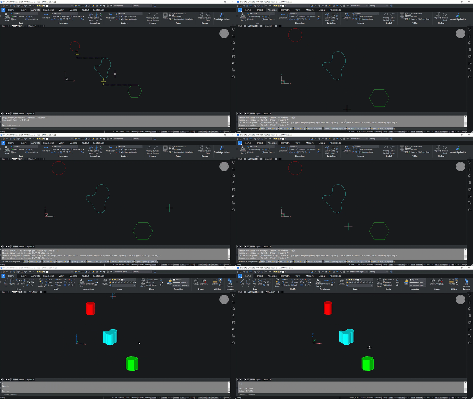
In the example below, we have 3D objects which are kept in different levels in the Z axis direction.
You can use the Arrange command and select these three objects, and then click on the Z axis.
The lower align aligns the lower bound of each entity with the lower bound of the selection bounding box in the Z axis direction. The lower bound is defined by the face of the bounding box placed at the smallest coordinate along the Z axis. In this illustration you can see the bounding boxes of the entities as well as the selection set as cuboids are made up of dashed line types. If you click on lower align, you’ll see that the lower bounds are perfectly aligned.
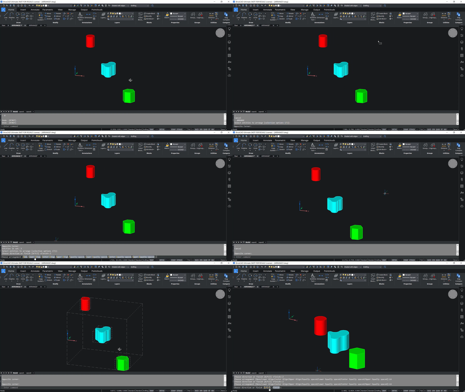
Next, we click on Z axis again, and on center align. Center align aligns the center bounds of the entities and the selection box, as we have seen in the case of X and Y axis.
Next, we move to the Z axis, and click on upper align. Upper align aligns the upper bounds of the entities and the selection bounding box in the Z axis direction. If the Z axis is selected once more, the distance between consecutive entities will be the same in the Z axis direction within the selection bounding box. Now you can see that the distance between these two entities, as well as these two entities, is the same.
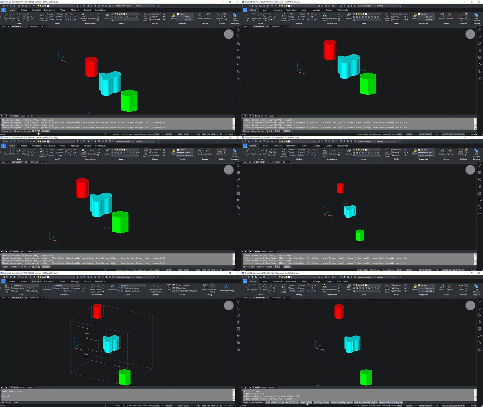
You also have access to options such as lower equally spaced, center equally spaced, and upper equally spaced. Again, each of these alignment options are similar to what we have already seen in the case of X and Y axis, but in this case these alignment options are applicable in the Z axis direction.
If you'd like to know more about working with commands in BricsCAD® V22 you can check out the full video on the Bricsys YouTube channel.
Get started with BricsCAD today!
Buy BricsCAD or download the 30-day free trial now and discover how you can accelerate your time to deliverable with BricsCAD.
Have you used the ARRANGE command and have some ideas or suggestions?
Fantastic! We love hearing your thoughts on BricsCAD® – all feedback is welcome, whether good or bad. The best way to tell us what you think about BricsCAD is to send us a support request; our support team will gladly help.
Want more BricsCAD tips and tricks?
If you're curious about what else you can do in BricsCAD, check out our YouTube channel to learn more about BricsCAD's features and commands, or take a peek at the rest of the Bricsys blog.

