ExpressTools is a collection of Productivity Tools that provides additional options and possibilities in BricsCAD®. Let’s have a look at some of the commands and tools included in BricsCAD’s ExpressTools.
How to access ExpressTools in BricsCAD®.
In previous versions of BricsCAD, you need to install ExpressTools from the application catalog. However, in BricsCAD V23 ExpressTools is a part of its native functionality.
To access ExpressTools in BricsCAD V23, click on the ExpressTools ribbon tab, and you'll find all the ExpressTools available categorized across various ribbon panels.
Each ribbon panel contains several commands and a fly-out to access additional commands.
Let's look at some of the most commonly used ExpressTools and how to use them!
Arc Text Tool
The Arc Text tool creates a text that follows a selected arc.
- Access the tool by clicking on the icon in the panel or use the command line and type in ARCTEXT.
- Click on the Arc Text tool.
- Choose whether you want to select an arc or an Arc Aligned Text.
- Type your chosen text into the textbox. In this example, we used Arc Aligned Text.
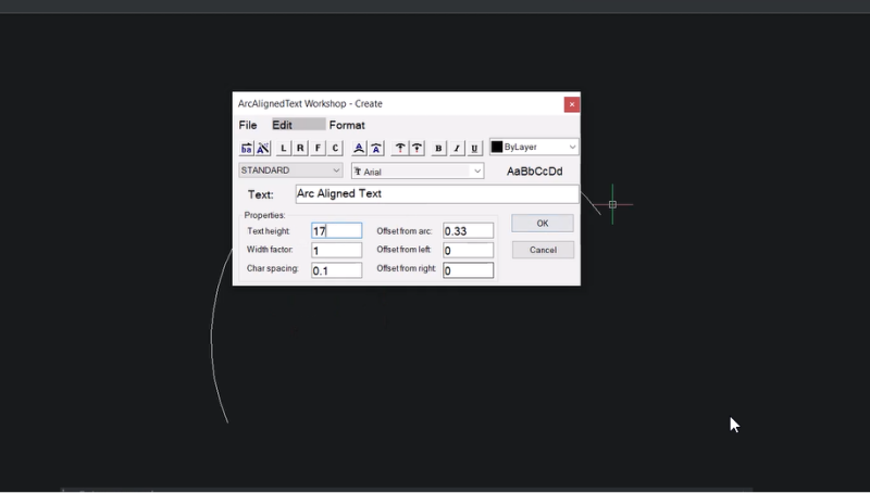
- Choose the height of your text. In this example, we have set the text height to seventeen units.
- Click OK, and the text is now written along the arc.
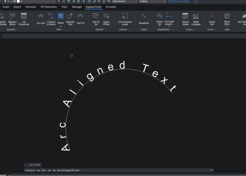
How to edit an Arc Text
- Click on Arc text.
- Select the text you want to edit.
- Edit the text.
Explode Text Tool
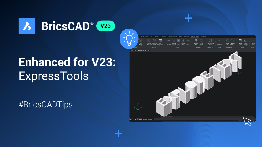
The Explode text tool lets you explode a text entity into polylines.
- Click on Explode Text or use the TXTEXP command.
- Select the text you want to explode.
- Hit Enter.
- You have converted the text to 2D polylines.
- Next, use the JOIN command to join all segments to single polylines.
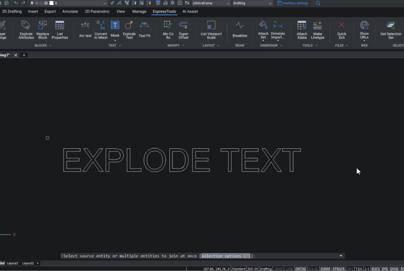
- You can change the view's direction using the Look From widget to get a top front left view.
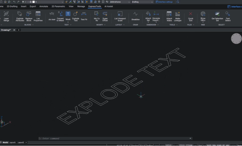
- Now, let's extrude this text to a certain height.
- Change the visual style to Shaded with Edges.
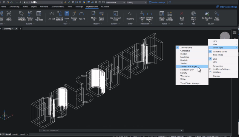
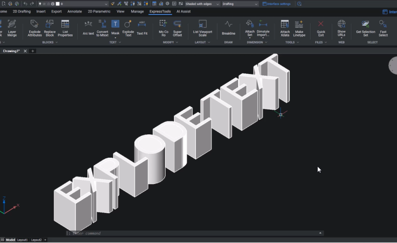
Once you explode a text to polylines, it can be edited in various ways, which you can't do with standard text.
Fast Select
The FS command allows you to select entities that touch a specified entity.
Let's use this example – we want to select all the trees on the path's boundaries.
- Click on Fast Select or use the FS command, and select the path.
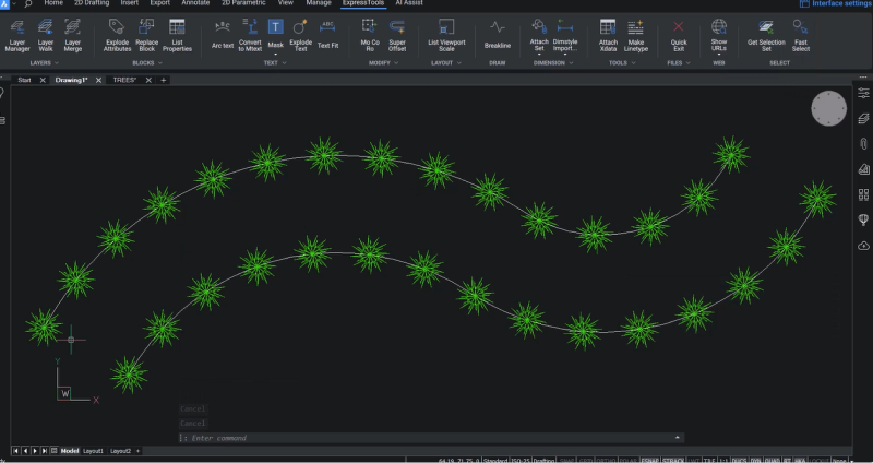
- Now, you can see that all the trees are selected because all the entities in the tree are touching the path.
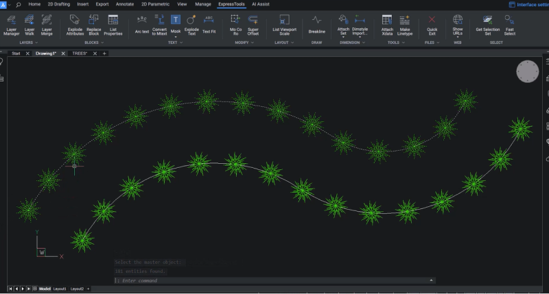
- When you edit the specified entity, the trees are automatically selected.
Make Line Type Tool
Using the Make Line Type button or MKLTYPE command, you can create a line type based on selected entities.
- For this example, let's create a line and some text.
- We want to represent steam lines using this line type, so we chose Steam as my text.
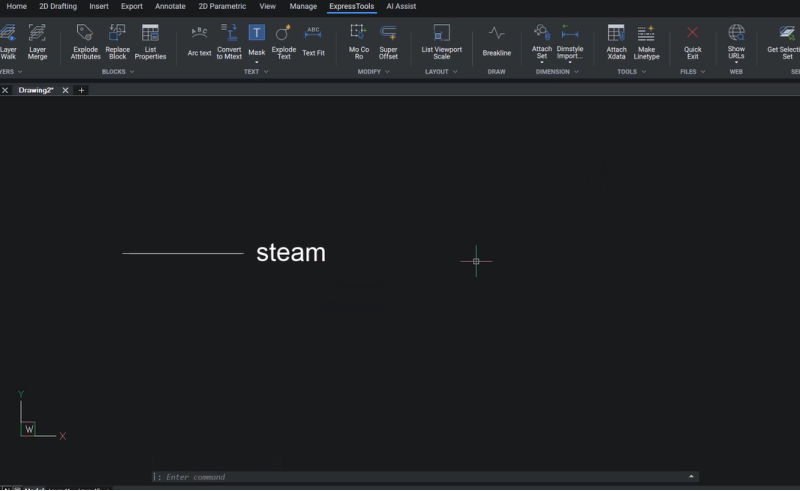
- Now, create a line type using these entities.
- Click on Make Line Type and create a line type file. In this example, we named the file as Steam.
- Click on Save.
- For this example, we have used "Steam" as the line type name and "Steam pipelines" as the optional description.
- Next, specify the start point and endpoint for the line type definition.
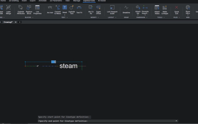
- Select the entities using a window.
- You'll see a message saying, "STEAM Linetype was created and loaded."
- Click on the Home tab and choose STEAM line type as the current line type.
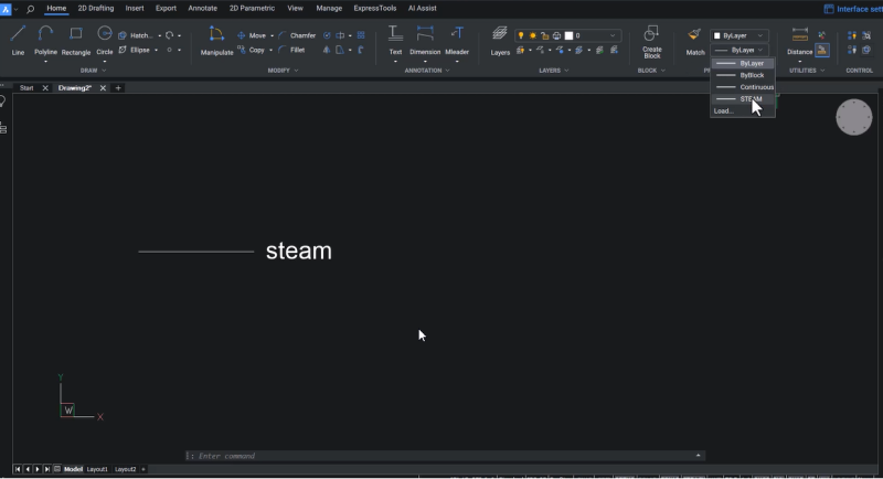
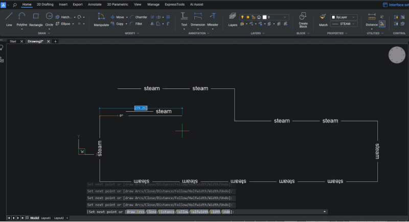
- Create a polyline using this line type, and you will see that the polyline is drawn with that particular line type.
Super Offset Command
Super Offset (EXOFFSET) is an enhanced version of the offset command with some additional options.
- In this drawing, these two wall lines exist in the walls and foundation layers.
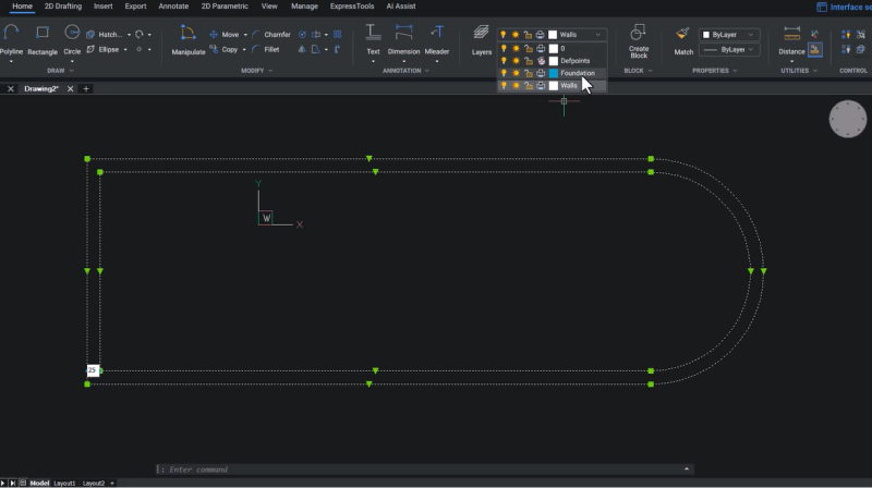
- Let's execute the Super Offset command (EXOFFSET).
- Now, you are asked for the offset distance. In this example, we chose five as the offset distance.
- Click on options to see three options: Distance, Layer, and Gap Type.
- We have already set the distance, so click on layer.
- Here, there are two options: Source and Current. Source keeps the offset object in the source layer, whereas Current keeps it in the current layer.
- For this example, we chose current – click on current and hit Enter.
- Now click on Gap type and choose Fillet.
- Hit Enter.
- Select the entity to offset and the site offset.
You can see that the offset entity was created in the current layer.
Since we chose the Gap Type as Fillet, you can see the fillets are included when you look at the corners. 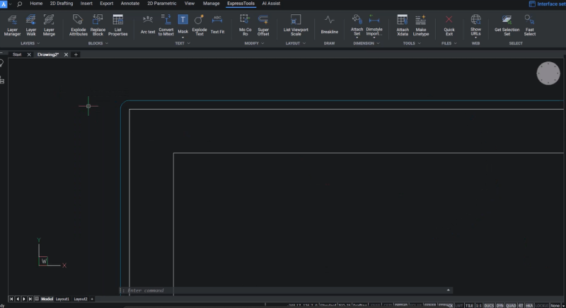
Similarly, you can also go for chamfer as the gap type.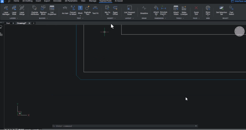
Quick Exit Command
- Quick exit (QQUIT) command quickly closes all drawings and exits BricsCAD.
- BricsCAD will ask you if you want to save the files when you click on this option.
- Click on Yes to save the files, and you can exit BricsCAD.
Want to try ExpressTools in BricsCAD V23?
Download the 30-day free trial now and start exploring BricsCAD V23.
Watch the video!
Check out the YouTube tutorial to watch ExpressTools in action!
Have you used ExpressTools and have some ideas or suggestions?
Fantastic! We love hearing your thoughts on BricsCAD® – all feedback is welcome, whether good or bad. The best way to tell us what you think about BricsCAD is to send us a support request; our support team will gladly help.
Want more BricsCAD tips and tricks?
If you're curious about what else you can do in BricsCAD, check out our YouTube channel to learn more about BricsCAD's features and commands, or take a peek at the rest of the Bricsys blog.
