
Welcome back to the Grasshopper®-BricsCAD® connection blog post series! In the previous post, we looked at the technology behind the Grasshopper-BricsCAD connection. In this post, you will learn how to write a simple Grasshopper script to create a parametric "frame" in BricsCAD. In the next post, you will learn how to add BIM data.
You can follow along step by step or cheat and download the ZIP-folder. Where you'll find the completed scripts.

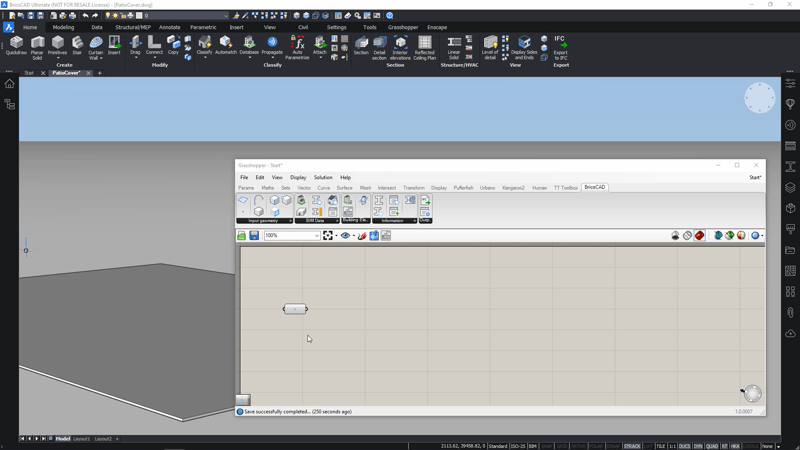
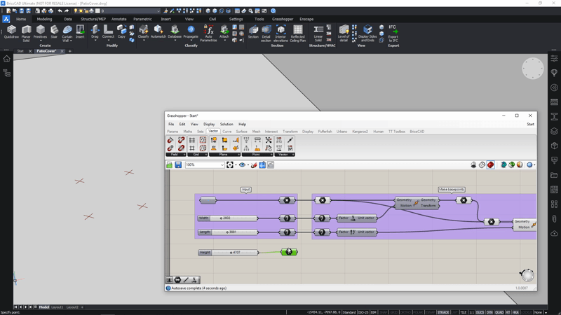
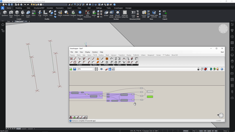
By the end of this post, you should have something like this. This is the framework that will become the patio cover
Get started
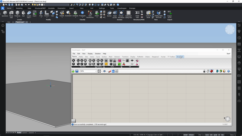
First of all, it is important that your Grasshopper-BricsCAD connection is set up correctly. To do this see the Grasshopper-BricsCAD connection help page. Once your connection is up and running, you should see a new tab in the Ribbon, this allows you to launch both Rhino and Grasshopper from within BricsCAD. For this exercise we will only use Grasshopper but you should know that Rhino is actually running in the background anyhow.

If you are still unsure of the Grasshopper workflow, take a look at Part 1 -- What is Generative Design?.
Launch a new drawing
- To start, launch a new BricsCAD drawing. For this example I use millimeters, but you can also work in imperial, if you prefer.
- Save the drawing on your computer and launch the Grasshopper command.
- Now save the Grasshopper file and you are ready to go!
The input
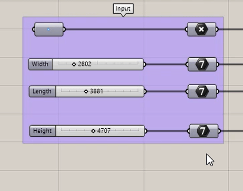
Next, define the input point of the patio cover. There are several ways to do this, for example, you could specify a rectangle in BricsCAD as a starting entity and then use the corner points of that rectangle as base points. However, for this exercise, I will use a single, 'localization' starting point because this allows the most flexibility later in the script.
The steps
- Use the Box command to make a base slab in BricsCAD.

- Drag and drop a BricsCAD Point component to the Grasshopper canvas, from within the Grasshopper Components Palette 'BricsCAD > Input Geometry'.
- Right-click on the component, choose 'Set input point' and choose a location on the top of the slab where you want to define a virtual point.
Note you can't use a regular Rhino Point as input. If you use a Rhino Point, Grasshopper will check the Rhino workspace and not to the BricsCAD workspace. - Link the Point to a Rhino-point Params > Geometry > Point. This will allow you to work with it further and will create a clean script.
- (Optional) To rename this component (right-click) it. This is handy for maintaining an overview of what this component contains. For this example change the name to 'Corner 1'.

- (Optional) To keep things even cleaner, select the two components and group them: right-click and select 'Group'.
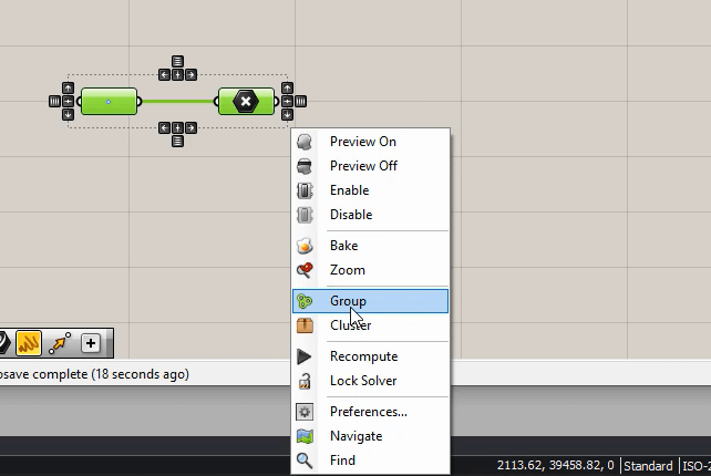
- (Optional) Rename this group to 'Input' group (right-click to rename).


Start simple
Although it's tempting to start by trying to create the most complex shapes you can imagine, it's best to start simple. Use the Move command to 'copy' the localization point to make the other three base points.
The steps
- Insert another Rhino-point.
- Link it to the Rhino-point of the 'Input' group. This point will be the start of a new group. The new group will make the 4 base points of the patio.

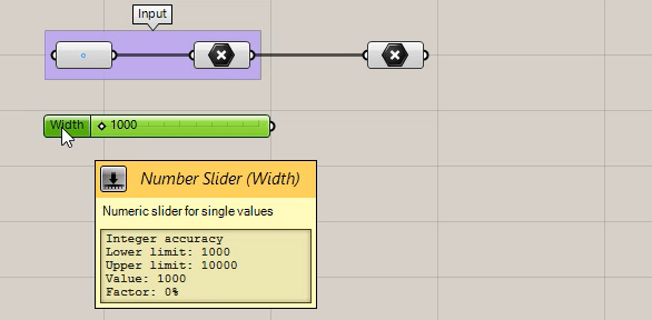
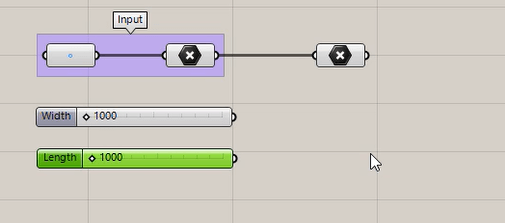
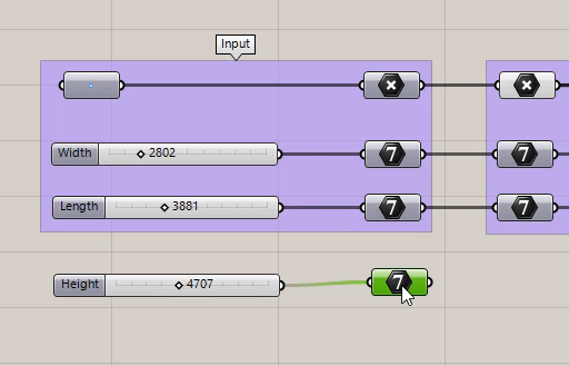
- Make a slider for the width with a range of 1 -- 10 meters. To do that:
- Double-click on the Grasshopper canvas
- Type in 1000<10000 in the search field. This makes a slider (in the units of our drawing, so mm).
- Right-click on the name to rename this slider to 'Width'.
- Copy-paste the previous slider and rename it 'Length'.
- Add the two sliders to the 'Input' group. Select them, right-click on the 'Input' group and choose 'Add to group'.
- To tidy things up, add four Integer components to the canvas, name two 'Width' and two 'Length' and link them to the corresponding sliders. Put one of each in the 'Input' group.
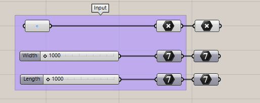
- Add a Move-component Transform > Euclidean > Move to the canvas.
- Link it to 'Corner 1' point in the 'Geometry' field.
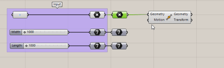
- Now try to link the width integer to the 'Motion' field. A warning will display and the component will turn red. This means, that the input type is not valid (see the red balloon to read the full error message).
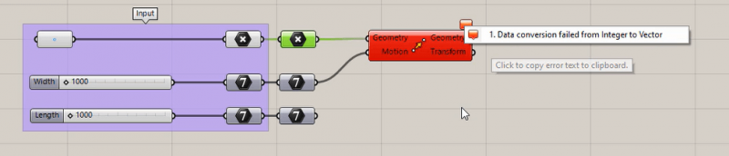 How come? Grasshopper just doesn't know in which way you want the point to be move over the integer value. Luckily there is a mathematical way to define this and it is called a 'vector'.
A vector can be defined by two points the start point and the endpoint (through the 'Vector 2Pt'-component). It defines a direction and a length. If you apply this vector to the 'Motion'-field, it will let the component know which translation you want your geometry to undergo.
Alternatively, a vector can be represented by a unit-vector (a vector with length one) and a length. To do that, you can use the unit-vector that points in the x-direction for the Width, and the unit-vector in the y-direction for the Length. - Add both a 'Unit X' and 'Unit Y' component Vector > Vector to your canvas and as their length (or 'Factor' -- with which you want to scale this unit-vector) you can link them to the 'Width' and the 'Length' integers.

- Finally, link the 'Unit X' component to the 'Motion' field.
You will now see a preview point that is translated according to the slider value in the x-direction.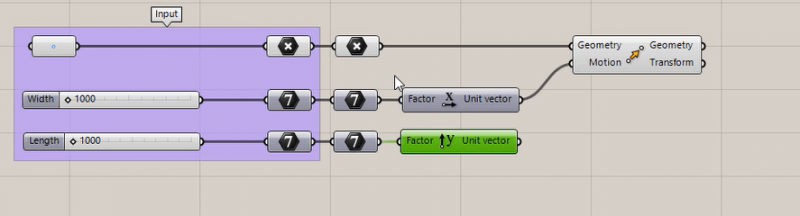
You can put this one again in a 'Point' component that you, for example, name 'Corner 2'.
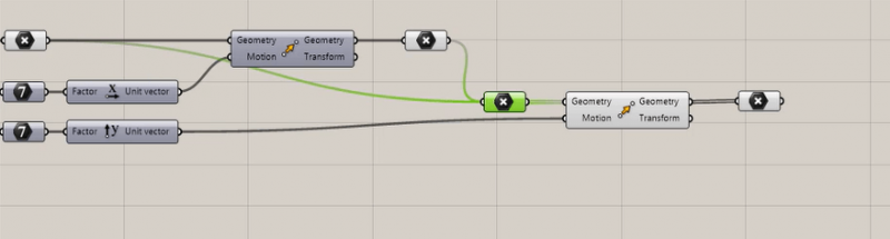
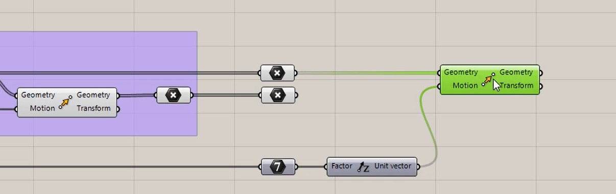
Note: to see these points in BricsCAD you need to set PDMODE to 3. - Make a new Rhino 'Point' component and input both 'Corner 1' and 'Corner 2'. Hold down Shift while you link to the second corner point. Name this point 'Corner 1 and 2'.
- Make a 'Move' component. This time add 'Corner 1 and 2' to the 'Geometry' field.
- Add the y-vector to the 'Motion' field and ta-da: four points have been created!

- Put the two new points (the output of the last 'Move') in a new Rhino 'Point' component and name this component 'Corner 3 and 4'.
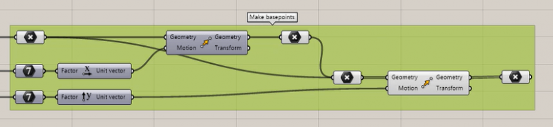
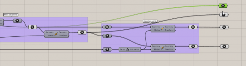
- Group all of the ungrouped elements in a group called 'Make base points'.


 How come? Grasshopper just doesn't know in which way you want the point to be move over the integer value. Luckily there is a mathematical way to define this and it is called a 'vector'.


You should now have something that looks like this:

Play around
You can now very clearly see the structure of your script appearing. You have an Input group, which defines the input parameters and geometry and you have a first functional group, that makes the base points. You should be able to clearly see the input components at the start of the group and an output component at the end of the group.
So now it is time to play around!

The steps
- If you did not manage to complete the previous steps, you can download this ZIP-folder and open the 'Start simple_end.gh' file.
Note: You might need to set an input point, as described above.
If you have different .dwg's open, you might need to link the .gh script to the open .dwg file manually. Click the blue 'Link' button in the Canvas Toolbar of the Grasshopper environment. - Now start playing around! Change up the values of the sliders: you'll see your points move around.
- Change the location of your input point: right-click the BricsCAD 'Point' component and choose 'Set one point'. Pick a new location on top of the slab. You'll now see the entire group of points move.
Tip This is most easily done when the BricsCAD '3D Nearest'-snap is on.
Practice makes perfect!
Now it is time for you to practice your skills and make four more points that will, later on, define the endpoints of the columns. Hint: you will need a new input: a height parameter!
The steps
- Make a new slider for the height. (See step 2 of 'Start Simple').
- Make a duplicate of 'Corner 1 and 2' and of 'Corner 3 and 4'.
- Make a new 'Move' component. Input a 'Unit Z' in the 'Motion' field (with factor 'Height').
- Input the duplicate of 'Corner 1 and 2' in the 'Geometry' field.
- Repeat steps 2 and 3 with 'Corner 3 and 4'. You now have the endpoints of your future columns.

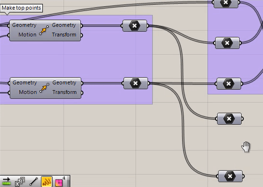
- To tidy up your script:
- Make a 'Make top points' group out of the new components.
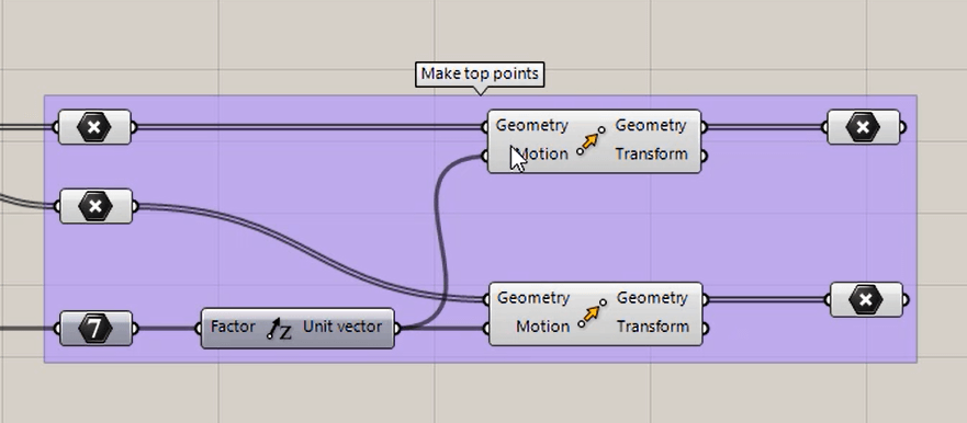
- Add the input from step 1 to the input group.
- To view only the outputs of the groups, select all the components you don't want to see (Shift select them or make a selection window over all of them) and right-click on the canvas and choose 'Preview off'.
- Make a 'Make top points' group out of the new components.


If you want to skip this: download this ZIP-folder, which contains the 'Practice makes perfect_end.gh' script.
Make the column lines
Let's end this blogpost with a (excuse the pun) concrete result and learn how to make the centerlines of the columns and beams that will form the frame of the patio.
The steps
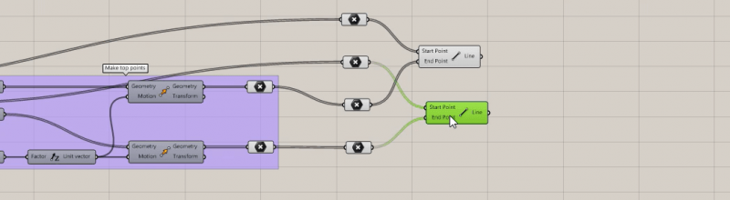
- To start the new group with clean input, duplicate the point components (the outputs of the previous groups).
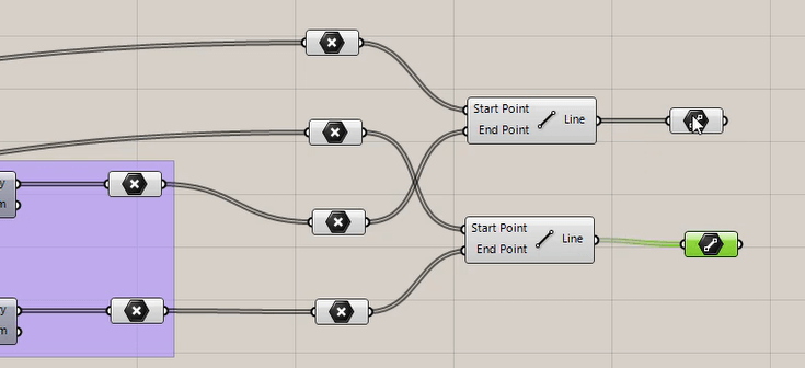
- Make lines between the bottom points and the top points. To do that:
- Add a 'Line' component to the canvas (Curve > Primitive).
- Add the duplicated 'Corner 1 and 2' to the 'Start Point' field.
- Add the duplicated 'Top 1 and 2' to the 'End Point' field of the Line component.
- Now repeat step 2 for the third and fourth corners and top points.
- You should now have the centerlines of your columns and can start to play with the height parameter. On-screen you will see them stretch or crimp.
- To tidy up your script:
- Add two 'Line' components (now the one from Params > Geometry)
- Link them up to the components from steps 2 and 3 and rename them 'First columns' and 'End columns'.
- Group all these components in a 'Define columns' group and hide all previews except this group's output. Now you should see only the columns' centerlines.
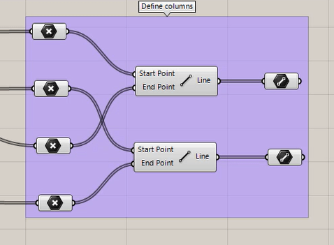


You should now have something that looks like this:

Complete the frame
And finally, it is time to complete the frame along with the centerlines of the beams. Again there are many options for you to achieve the same result, but perhaps the simplest way is:
The steps
- For the beams, return back to the top points and copy the output components. This will become the input of the next group.
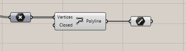
- Now make the beams using the 'Polyline' component.
Note: You can input a collection of points and a polyline to be made in between them. This allows you to easily make a line from your collection of points.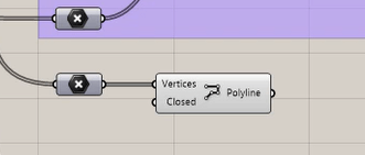
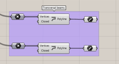
- Name this line (in a 'Line' component) 'First beam'.
- Repeat steps 2 and 3 to make name this component 'End beam'.
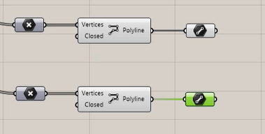
- To tidy up group these components, name it 'Make transversal beams'.


Congratulations! You made the framework for our patio cover! Be sure to check in with the next blog post to get the hang of using BricsCAD BIM's profiles in Grasshopper and much more.
Learn Grasshopper for BricsCAD today
Get Grasshopper for BricsCAD BIM
Keep reading:
- What is generative design?
- The Technology
- How to Write a Simple Script

Fleur, EMEA Technical Pre-Sales Team Lead, brings her natural talent and enthusiasm for technology to Bricsys. Her passion is to pass on her expertise to anyone that even considers saying the word "BIM" and she is constantly looking for innovation and improvements. If you ever need someone to listen to your next great BIM idea, feel free to drop her a line!
