Search

3D Modelling

Dynamic User Coordinate Systems in BricsCAD® Shape - Joachim's Journey Part 15

By Joachim Corijn 3 min February 24, 2020
Dynamic User Coordinate Systems in BricsCAD® Shape - Joachim's Journey Part 15

This time, we go down-under to the weird and wonderful land of Dynamic User Coordinate Systems (DUCS). This is a really powerful tool that allows you to draw on different planes in BricsCAD Shape. Not just on the "flat" x/y plane but the "vertical" z/y, z/x planes and pretty much any orientation in between.

What are the X Y and Z axes?

Imagine that X is "left and right" and Y "forward and backward" and Z is "up and down".

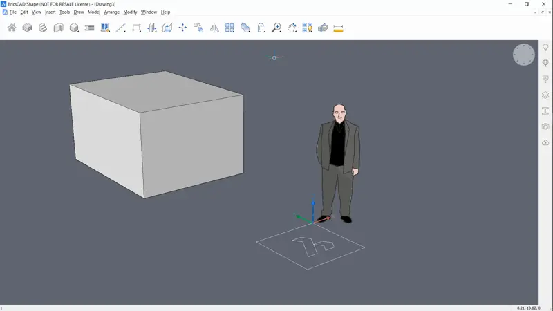
By default, BricsCAD® Shape draws along the X/Y plane and the 0 point on the Z-axis. Just think about it as though it's a large sheet of paper laid flat on the ground. This determines where you can start drawing a 2D or 3D object.

Dynamic User Coordinate Systems in BricsCAD<sup>®</sup> Shape -flat logo-1024x576

Here you can see that the logo is resting flat on the x/y pane "the ground". This is the standard drawing plane for BricsCAD Shape.

How to draw on a different plane in BricsCAD Shape

If you want to draw at a different angle you need to change the UCS (User Coordinate System) -- "move the sheet of paper". The good news is that this is easy to do BricsCAD Shape.

You see this thing?:

Dynamic User Coordinate Systems in BricsCAD<sup>®</sup> Shape -UCS

That's the UCSIcon. It basically tells you where the 0,0,0 coordinate is and which direction the x, y and z axes are.

To change the UCS (user coordinate system):

  1. If I have DUCS turned "on" (hit F6 to toggle it on and off)
  2. Execute a command.
  3. Hover over a face that represents the correct plane.
  4. Hit Shift to fix the UCS.
  5. Start drawing, the UCS will remain fixed for the duration of this command.Dynamic User Coordinate Systems in BricsCAD<sup>®</sup> Shape -dynamic cube

Did you know?

It doesn't just work on flat surfaces, you can also use it on curves too!

Dynamic User Coordinate Systems in BricsCAD<sup>®</sup> Shape -dynamic spher

Curiosity not satisfied? Learn more about UCS.

What's next?

In this CAD lesson, we looked at ways to draw on different planes in BricsCAD Shape. In the next lesson, we'll take a look at ways to export your models.


Download BricsCAD Shape free

Watch the webinar "BricsCAD Shape in 10 minutes"


More CAD lessons:

  1. What is BricsCAD Shape?
  2. Download & Install
  3. Get started
  4. The Interface
  5. Commands
  6. Selecting Objects
  7. Transform
  8. Materials
  9. Components
  10. View Styles
  11. Layers
  12. Editing Entities
  13. More way to Edit Entities
  14. Arrays
  15. Dynamic User Coordinate Systems
  16. Export files and images
  17. Lazy Man's Guide to BricsCAD Shape
Joachim Corijn

by Joachim Corijn - Global Marketing Operations Manager at Bricsys®

Global Marketing Operations Manager at Bricsys® at Bricsys and an absolute CAD newbie (but having fun). Fan of hiking & cycling. Into the wild, avoid tourist traps.

July 23, 2024 3 min

Polyline Editing in BricsCAD

Polylines offer an array of functionalities for 3D modeling. Polylines consist of connected line or arc segments that act as a single entity. Each segment can have a constant or varied width, making polylines versatile for creating 3D models.

In this tutorial, we'll explore the various methods you can use to edit a polyline in BricsCAD.

July 15, 2024 3 min

Optimize and validate assembly designs in BricsCAD Mechanical V24.2

The latest release of BricsCAD Mechanical V24.2 introduces enhanced features intended to make your assembly manual creation and inspection workflows more efficient. With the integration of Design for Manufacture and Assembly (DFMA) optimization and validation workflows, users can streamline the assembly process, reduce manufacturing complexities, and identify cost-effective design changes early on.

Follow us on social media